Tektronix 492 First Mixer
Mixer Diode Failure
The performance of this machine depends heavily on the first mixer, which converts the incoming RF to an IF at either 829MHz or 2072MHz. As received, it worked fine, but after a week or two it suddenly showed about 30dB attenuation. The 100MHz calibration signal was barely visible. I ruled out everything except the first mixer and first LO, so I bought a Mini-Circuits ZFM-15 mixer (also on eBay) and tried it out on the external mixer port. The ZFM-15 worked fine, so the problem had to be the first mixer.
The Tek 492's first mixer is a stainless steel box with a stripline hybrid and phase shifter printed on an apparently aluminum-clad high-frequency PCB material. The diodes are in a removable module which the manual takes great care to explain is sensitive to damage from everything. Checking with a multimeter showed that one of the two mixer diodes was almost open.
The mixer diode assembly is:
- Beam lead diodes, which appear to be
- Welded (ultrasonically?) to
- Gold traces printed on a
- Fused quartz substrate, with
- Gold ribbons, also welded, connecting to a
- High-frequency laminate, which is glued to a
- Stainless steel carrier plate, grounded to the frame through a
- Conductive O-ring.
Short version: Not something I can duplicate, and they don't appear on eBay.
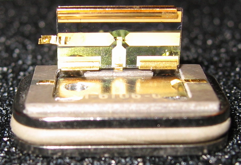
This picture shows the diode module with the quartz substrate held up by one of the three gold ribbons. The gold ribbons are the contacts between the diode module and the stripline board in the mixer. Each ribbon was folded over at the board. I cut the left ribbon at the fold since it was not welded all the way through. The welds on the right ribbon broke. The welds on the center ribbon broke some time after this picture was taken.
The screw hole on the left of the carrier block has a set screw that is used to "null a start spur on band 1", according to the manual. This might refer to the 0Hz response, in which case mine was not adjusted correctly when I got it, as that response has always been off-screen.
Interim Solution
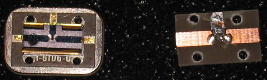
I etched a replacement board in my kitchen. It's FR4 with the mixer diodes from an old cell phone on it. It works to at least 1.5GHz, but seems to really trail off above 2GHz. I don't have a good source over 2GHz so I can't characterize it well, but this is good enough for zero cost. The cell phone diode might actually be an HSMS-2822 or similar as it has the same topmark.
This board produced a spurious response at 1.1GHz until I put the metal carrier block behind it. It was being grounded only through the mounting screws.
Improvements
I tried two other diodes: HSMS-2822 and HSMS-8202. There was no significant difference in performance at 2GHz.I have replaced the PCB with one produced with holes in the right places and tin plating.
I have tested the replacement diodes with input signals up to 9.5GHz and they work fine, although the noise floor seems high on the upper bands.
A proper replacement would be the HSCH-5330, which Newark stocks. These are expensive ($20 each), fragile, and are supposed to be welded in place.