DAC Test
Submitted by ben on Mon, 10/18/2010 - 17:18
Contents:
Subjects:
I built this board to test the DAC and antialiasing filters for my function generator. It plugs into the Digilent XC3S1600E board (no longer sold, but this will probably work). The DAC is driven by the FPGA at 200MSa/s.
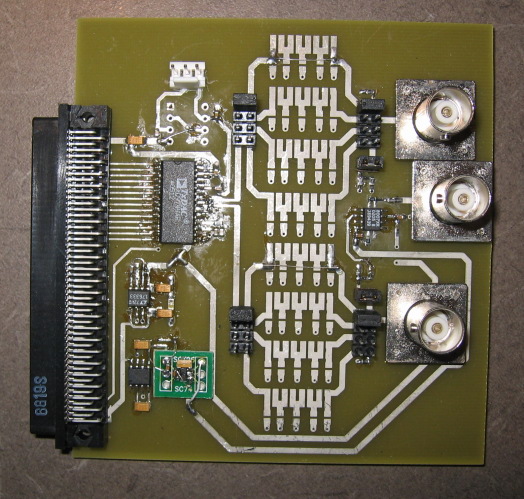
Assembled Board
In this photo, no filters are populated. There is space for four jumper-selectable filters for the positive and negative DAC outputs. Each DAC output can be connected to a BNC jack or the two can be combined by an op-amp to provide a buffered 50-ohm output.
There is a little board error on one of the power supplies. The 5-pin SOT23 pinout in PCB's libraries has the pin numbers in the wrong order, so I used an adapter board to mount the chip correctly.
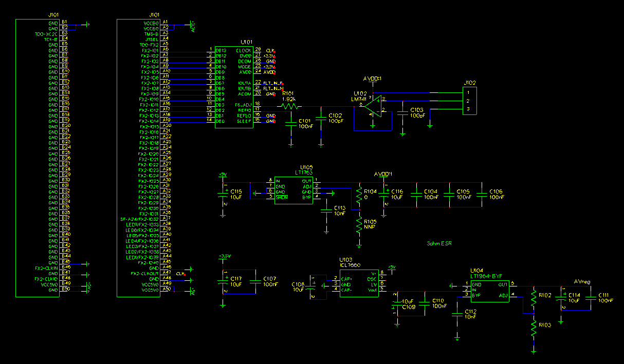
Schematic of DAC Section
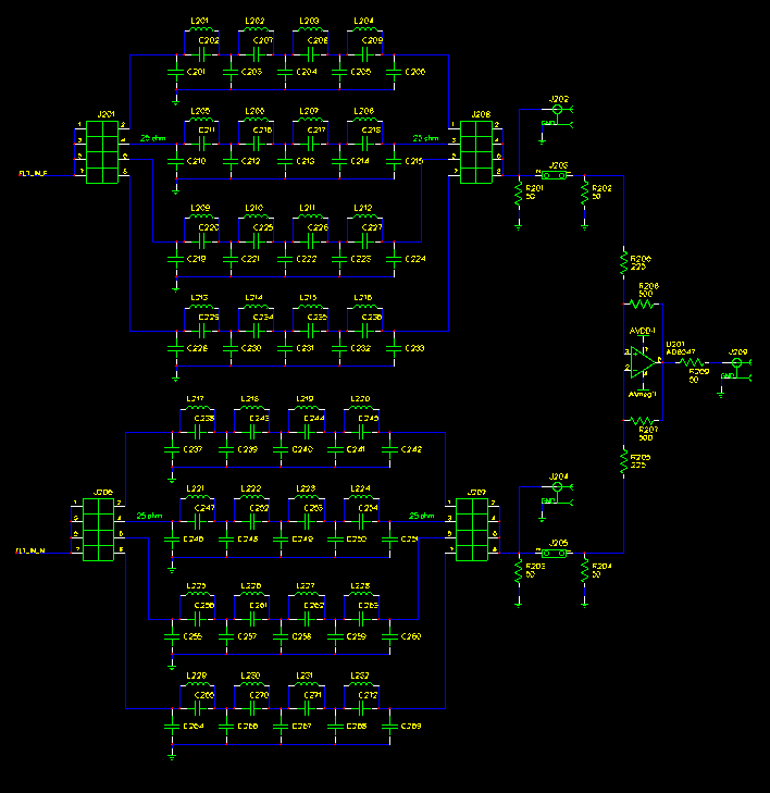
Schematic of Filter Section